
Please Read This First:
Build Your Own Clone does not offer technical support
or parts for modifications. Please do not ask. Do not
email with questions concerning modifications. All parts
for these mods can be found at electronics distributors
such as www.digikey.com or even RadioShack and there
are DIY FX forums such as the forum at
diystompboxes.com where you can get advice.
Changing the tone of your Fuzz Face:
This is probably the most common mod that is done to the FF circuit. Many people
consider the FF to be too bassy. The easiest mod is changing the input capacitor to a
smaller value
1. Changing the input capacitor (easy) - The input capacitor is the 2uF
electrolytic capacitor. Replacing this cap with a smaller cap will cut some of the bass
and allow more mids to come through. The smaller the cap, the more bass you will
cut and eventually will begin to cut the mids as well leaving just treble. A good value
capacitor to replace the 2uF with is a 0.047uF. This will still give you a nice full
sounding fuzz, but not so overly bassy. Switching to a 0.033uF or 0.022uF will give
you a fuzz with mids as the dominant frequency. At about 0.022uf to 0.01uF, you will
begin to loose some gain and your fuzz will start to become more of an overdrive.
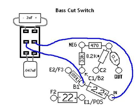
2. Input capacitor switch (moderate) - This is a little more difficult and will
require you to drill another hole in your enclosure. A simple 2-way switch can be
made with a DPDT(double pole double throw) toggle switch and your 2 favorite input
capacitors. You can make it more elaborate with a 3-way DPDT toggle switch or a
rotary switch with at least 2 poles and as many positions as you want. Be sure to
remove the 2.2uF capacitor from the circuit board. You don't want 2 input capacitors
at the same time. Also note that smaller capacitors (less than 1uF) are most likely
going to be "metal film" caps. Unlike the 2uF aluminum electrolytic cap, metal film
caps are not polarized (no positive or negative ends) so you can stick them in any way
you like.
3. Tone Knob (difficult) - For the ultimate in tonal flexibility you can add a simple mid-scoop style tone knob. You'll need to drill another hole. You
will also need: B100K pot (linear taper), 33k resitro, 100k resistor, .0033uF capacitor, and .01uF capacitor. Your wiring should not look like the diagram
below. It's that way so you can see where all the wires go. Twist the leads on one end of both the 100K resistor and .01uf cap together and then bend
them to make a small loop that will serve as a solder lug. Solder the untwisted end of the .01uf cap to lug 3 of the b100k pot and the untwisted end of
the 100k resistor to lug 1 of the pot. This will give you the "old school" reverse treble to bass taper, but if you want a more conventional bass
counterclockwise-treble clockwise taper then switch lug 1 with lug 3. Do the same thing with the 33K resistor and .0033 cap but solder the untwisted end
of the cap to lug 1 and the untwisted end of the resistor to lug 3. The same pricipal applies here as well...if you want a bass to treble taper, then switch
lug 1 with lug 3. Remove the "wet signal out" wire from lug 3 of the level pot and solder it to the makeshift lug of the 33k resistor and the .0033uf cap.
Run a ground wire from the makeshift lug of the 100k resistor and the .01uf cap. finally run a wire from lug 2 of the tone pot to lug 3 of the level pot.
Transistors: Biasing, hybrids, and conversions:
IMPORTANT NOTE: If you are starting with a positive ground circuit that uses PNP
germanium transistors such as the OC75, then any silicon transistors you add MUST
BE PNP!!! BC213 and BC214 are PNP silicon workalikes for the BC108 and BC109.
If you are starting with a negative ground circuit that uses NPN silicon transistors
such as the BC109c then any germanium transistors you add MUST BE NPN!!! The
AC188 and AC187 are NPN germanium transistors. My advice to you if you want to
do any sort of hybrid or conversion mods, you should start with the PNP germanium
version. Because NPN germanium transistors are very rare and costly. PNP silicon
transistors are very common and only cost a few cents. If you already have the
negative ground silicon kit, you can convert it to positive by switching the battery
wires and replacing the transistors.
Some of these mods are not very difficult, but most people are scared of them because they are afraid they will damage the
transistors...especially germanium transistors. It's a good idea to pick up a digital multimeter if you plan to tinker with things of this nature
more than just once or twice. Try to get one that has transistor tester sockets as well.
Bias refers to the amount of negative voltage going to the collector (C2, the collector of transistor 2 in this case). It's the second transistor
that has the most influence on the final sound of the fuzzface. To measure the votage to the collector you set your multimeter to the
DCv setting that is closest to 9volts but not less. On most multimeters it would be 20 DCv. Then touch the red probe to C2 and the black
probe to ground. You should get a reading of somewhere between 4.5 and 5.5. 4.5v is the ideal collector voltage, but that doesn't
always mean that it will produce the best sound.
1. Adjusting the bias (easy) -This mod will change the "fartiness" of your fuzz. Change the 8.2K resistor. To increase collector
voltage, use a smaller resistor. To decrease collector voltage, use a larger resistor. Most people will want to decrease the collector
voltage. This will give the fuzz a smoother sound. Try replacing the 8.2k resistor with a 10k or 11K.
2. Hybrids (moderate) - Remember to use PNP transistors if your circuit is positive ground and NPN if your circuit is negative ground.
This mod can give you the best of both germanium and silicon. Since it is transistor 2 that has the most influence on the final sound of
your fuzz, most people like to use germanium for transistor 2 and silicon for transitor 1. That way, you will have a more "vintage"
sounding fuzz, but with a slight bit more gain and sustain. So changing one of the transistors is the obvious part of this mod. But
introducing a much higher gain silicon transistor to a circuit that is biased for germanium can sometimes cause feedback. If you are
getting feedback, you are going to want to change the 470ohm resistor. You will want to use a smaller value. Try between 390ohm -
330ohm.
3. Total Conversion Switch (very difficult) - This will essentially give you 2 pedals in one. You will need a 4PDT toggle switch. A
2 position/4 pole rotary switch will work as well, but will be messy and take up more room. Remove the transistors from your circuit board.
Designate one side of your toggle switch as germanium and the other as silicon. ONLY solder the emitter and collector of the transistors
to the toggle switch. I'm not going to go into great detail about where to solder each of the emmiters and collectors, just study the
diagram and use common sense. Follow the wires and see where they are going. Make sure that you line up the collector of the silicon
transistor with the collector of the germanium transistor and so on. Take the base leads of each transistor and twist them together with
their counterpart so that you form a makeshift solder lug. Then run wires from the makeshift solder lugs and the poles of the switch to their
appropriate places on the circuit board. C1 is connected directly to B2, so run a wire from the pole of C1 to the makeshift solder lug of
B2 and then another wire from the makeshift solder lug to C1/B2 on the circuit board.
You are most likely going to need to rebias when you switch from germanium to silicon. There are 2 solutions to this. 1 is that you can
simple replace the 470ohm resistor with one that will work for both Ge and Si. 390-360ohms will do the trick. Or if you want the most
tweekability, you can add a bias knob. Use a B1K (linear taper) pot. Remove the 470ohm resistor. Run a wire from one eyelet to lug 2
and another wire from lug 1 to the other eyelet.