
Silicon Version: If you are building the silicon version, you will
need to switch the polarity of the battery snap. For step 1 the
RED wire should go to the "NEG" eyelet. For step 2 the
BLACK wire should go to the solder lug of the RING of the "IN"
jack.
You are almost done! Just a few more steps.
Step 1:
Trim the BLACK wire of the battery snap so that it is the
proper length to reach from the "NEG" eyelet of the circuit
board (this is also where the 33k and 470ohm resistors
meet) to the BATTERY SPACE. It's a good idea to have a
9v handy so you can attach it to the snap and measure with
the battery actually in the space. You don't want to give the
black wire too much slack, but you want to give it enough
slack so that you can change your batter without having to
tug on the wires too much. Strip 3mm off the end of the
trimmed BLACK wire of the BATTERY SNAP and solder it
to the "NEG" eyelet. Your pedal should look like the pic
below when you have finished step 1. Note that the black
wire is passed under the IN jack to help keep it out of the
way when changing the battery. This is not necessary, but
it's a good idea to do so.
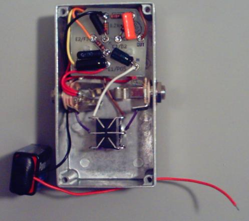
Step 2:
Trim the RED wire of the BATTERY SNAP so that it is the proper length to reach from the RING of the IN
jack to the BATTERY SPACE. The slack in the RED wire should be the same as the slack in the BLACK wire.
Strip 3mm off of the trimmed end of the RED wire and solder it to the RING of the IN jack. If you've done
everything correctly so far, this should be the only wire in the solder lug of the RING. Your pedal should look
like this when you have finished step 2.

You're done! Put your battery in the battery space and click here to continue on to "Finishing Touches and
Trouble Shooting"