
This is step 1 of populating the circuit boardof the fuzz clone
project. This may not be the project that you are building, but
the information pertains to all kits.
The red circle indicates where the solder joint will be made.
There will only be one solder joint made for each step in the
circuit board populating process. Even though there is only
one solder joint being made, there may be multiple component
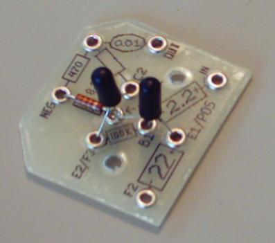
leads that are joined at this joint. Here, for example, there are
three different component leads at this joint: the collector of
transistor 1, the base of transistor 2, and the 33K resistor (see
orientating the transistor to learn more about the collector and
base). Each diagram will also be accompanied by a close-up
photograph of what the circuit board should look like at that
step in the populating process. If you look at the picture below
you will see transistor 1, transistor 2, and the 33K resistor all
soldered where the red circle in the diagram is. There will also
be correlating diagrams and photograph for the assembly and
wiring process.