
Step 1:
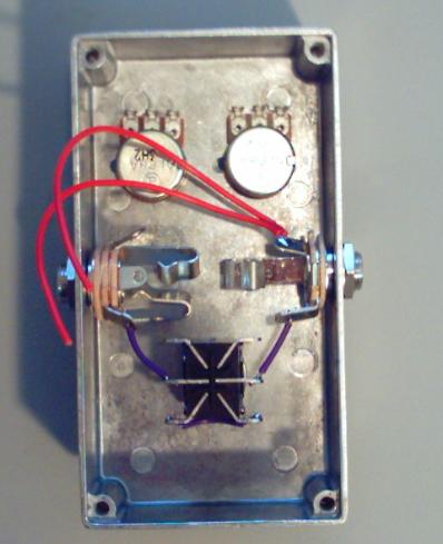
Cut 2 seperate 3" strands of red wire. Strip 3mm off only one
end of each of the the 2 wires. Solder the stripped ends of both
wires at the SLEEVE of the OUT jack. Your pedal should look
like the picture below when you finish step 1.
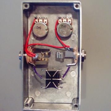
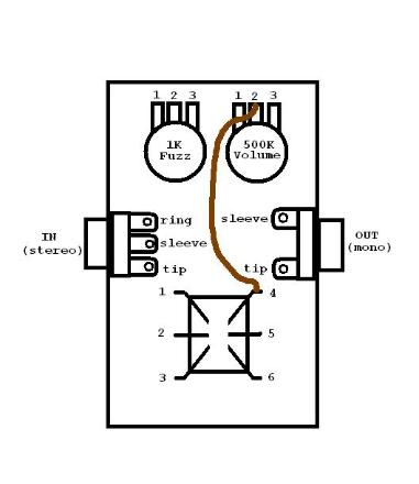
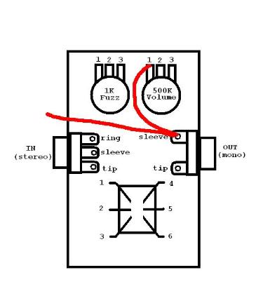
Step 2:
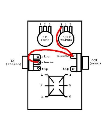
Trim one of the 2 wires so that is the proper length to connect the SLEEVE of the OUT jack with LUG 1 of the 500K
(volume) pot. You will want to keep this wire as short as possible, but you will want to give it enough slack so that
you can bend the wire down so that it runs along the inside of the enclosure wall. You do not want a "tight-rope".
Strip 3mm off the end of the strand of red wire that has been trimmed and then solder to LUG 1 of the 500K pot.
Your pedal should look like the picture below when you have finished step 2.
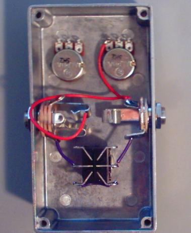
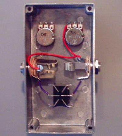
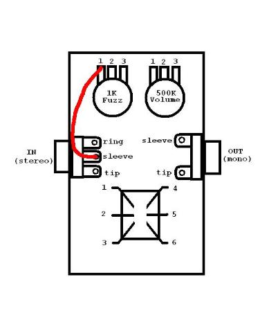
Step 3:
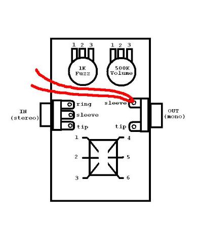
Trim the other red wire so that it is the proper length to connect the SLEEVE of the OUT jack with the SLEEVE of
the IN jack. Once again, you want to keep this wire as short as possible, but you want to leave enough slack so
that it can be bent down to run along the inside of the enclosure wall. Strip 3mm off the wire and solder to the
SLEEVE of the IN jack. Your pedal should look like the picture below when you are finished with step 3.