
Please read this carefully to make sure you understand it
completely. The first things to understand is that the transistor
has three leads: the emitter, the base, and the collector. On the
Mullard OC75, the base will be the very middle lead. The
collector will be denoted by a red paint dot. The emitter
will be the only lead that is left. In the build your own clone
fuzz wiring diagram, two transistors are used. The base of
transistor 1 is labeled B1. The base of transistor 2 is labeled B2.
The collector of transistor 1 is labeled C1. The collector of
transistor 2 is labeled C2. The emitter of transistor 1 is labeled
E1, and the emitter of transistor 2 is labeled E2. It does not
matter what transisor you use for transistor 1 or transistor 2.
Both transistors are gain matched, so it makes no difference
which transistor comes first. On the BC109c, the 3 lead wires
will be in a triangular formation that is offset to one side.
The Emitter will be denoted by a metal tab. The Base will
be in the center. The collector will be the the lead that is
across from the emitter.


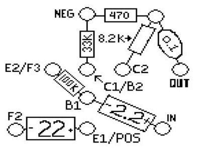
wiring diagram to show you where the transistors
go. There are only drawings for the capacitors
and resistors. The diagram only shows you
where to solder the emitter, base, and collector
of each transistor. So for example, you can see
by looking at the diagram above that the base of
transistor 1 is also connected to the 100K
resistor and the negative end of the 2.2uF
capacitor. Or another example would be the
collector of transistor 1, the base of transistor 2,
and the 33K resistor are all connected at the
same joint.
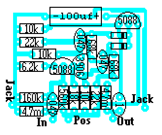
and JFETS, simple turn your transistor so that it matches
the picture on your circuit board layout sticker.
