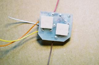

Step 1:
Install the nylon standoffs, but do not remove
the paper backings yet.
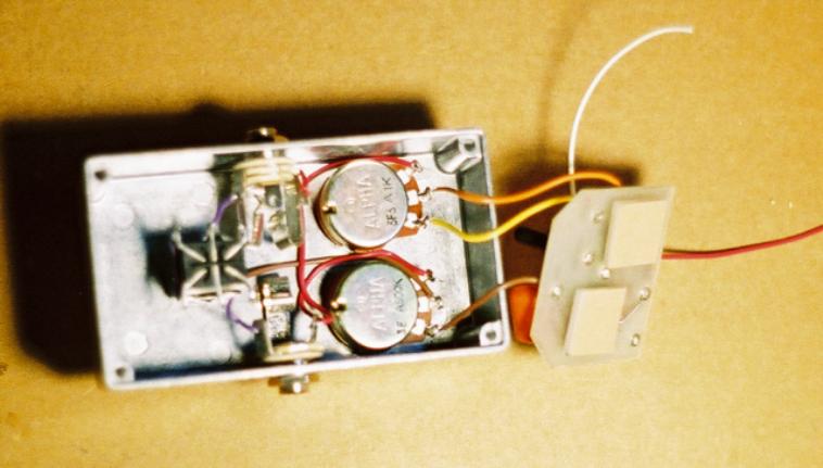
Step 2:
Trim the yellow, orange, and brown wires so that they are long
enough to reach the solder lugs if you are holding the top edge
of the circuit board against the top lip of the enclosure. They
should only be about 2 1/2" to 3" long. Strip 3mm off each of the
ends. Solder the orange wire coming off the S2 eyelet of the
circuit board to LUG 2 (center) of the 1K pot (sustain knob).
Solder the yellow wire coming off the S3 eyelet of the circuit
board to LUG3 of the 1K pot. Solder the brown wire coming off
the OUT eyelet of the circuit board to LUG3 of the 500K pot
(volume knob). Your pedal should look like the picture below
after Step 2.
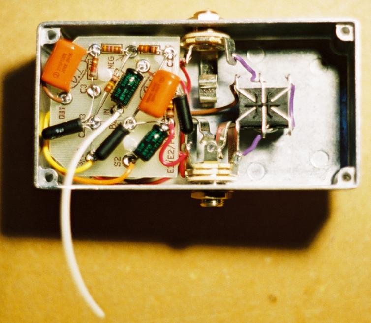
Step 3:
Trim the red wire coming off the POS eyelet of the circuit board so that it is long enough to reach the RING of the IN
JACK. Strip 3mm off of the end of the red wire and solder it to the RING of the IN JACK. NOTE: The distance from the
the POS eyelet and the Ring of the IN Jack will be very short. You may need to leave the red wire a little longer so that
you are able to strip on end of it. If you need to do so, just tuck the excess wire to one side out of the way. Your pedal
should look like the picture below when you are finished with step 3.
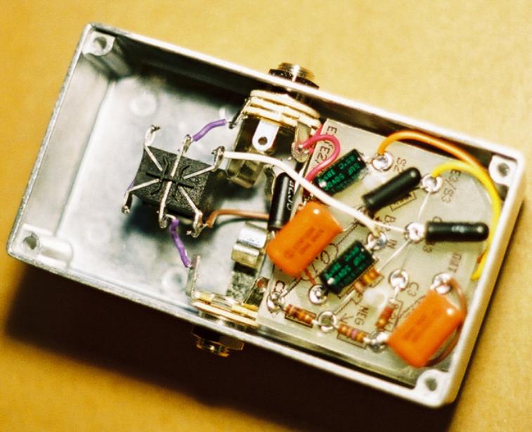
Step 4:
Trim the white wire coming off the IN eyelet so that it is long enough to reach LUG1 of the footswitch. Strip 3mm off of
the end of the white wire and solder it to LUG1 of the footswitch. Your pedal should look like the picture below when you
are done with step 4.
Go back to the Instruction Index and click on "Battery"