
Step 7:
Solder the Collector of Transistor 3 (C3) and the 8.2K
(gray/red/red) resistor to the eyelet highlighted in red in the
diagram below. Your circuit board should look like the picture
below when you are finished with step 7.

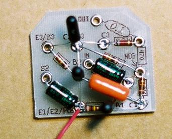
Step 8:
Solder the last 0.1uF Orange Drop capacitor, the 8.2K, and
470ohm (yellow/purple/brown) resistor to the eyelet highlighted
in red in the diagram below. Your circuit board should look like
the picture below when you have finished step 8.


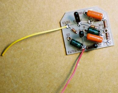
Step 9:
Strip 3mm off one end of 4 inches of yellow wire. Solder it to the eyelet highlighted in red in the diagram
below where it meets with the Emitter of Transistor 3 (E3) and the 100K resistor. Your circuit board
should look like the pic below when you are finished with step 9.

Step 10:
Strip 3mm off one end of 4 inches of orange wire and solder it to the eyelet highlighted in red on the
diagram below where it meets with the negative end of the 5uF capacitor. Your circuit board should
look like the picture below when you are finished with step 10.
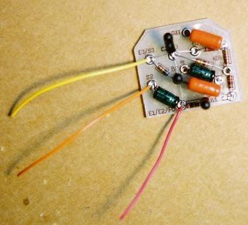

Step 11:
Strip 3mm off one end of 4 inches of brown wire and solder it to the eyelet highlighted in red on the
diagram below where it meets with the 0.1uF orange drop capacitor. Your circuit board should look
like the picture below when you are done with step 11.
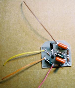

Step 12:
Strip 3mm off one end of 4 inches of white wire and solder it to the eyelet highlighted in red on the diagram
below where it meets with the negative end of the 5uF capacitor. Your circuit board should look like the picture
below when you are done with step 12.
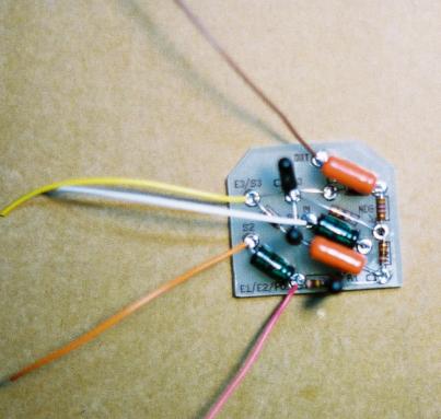

You are now finished populating your circuit board. Click on the next step in the instruction
index.