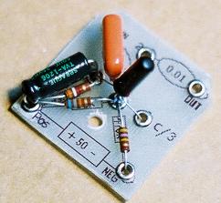

Step 1:
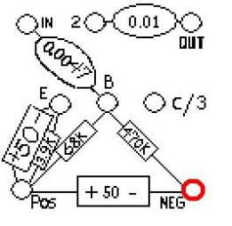
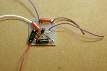
Solder the Base of the Transistor (B), the .0047uF orange drop
capacitor (472K), the 68K (blue/gray/orange) resistor, and the
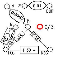
470K (yellow/purple/yellow) resistor to the eyelet highlighted in
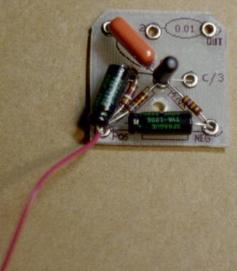
red in the diagram below. Your circuit board should look like
the picture below when you are finished with step 1.
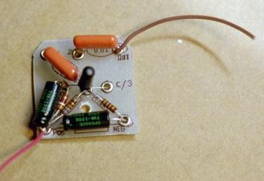
Step 3:
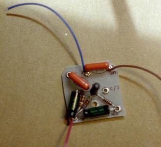
Clip 3 inches of red wire and strip 3mm off one end. Solder the red wire and positive end of the 2nd 50uF aluminum
electrolytic capacitor to the eyelet highlighted in red in the diagram below where they meet with the 3.9k resistor, 68k
resistor, and the positive end of the other 50uF cap. Your circuit board should look like the picture below when you
are done with step 3.


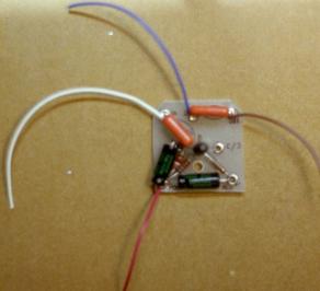

Step 8:
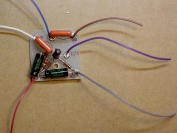
Strip 3mm off one end of the gray wire. Solder the gray wire to the eyelet highlighted in red in the diagram below
where it meets with the 470K resistor and the negative end of the 50uF cap. Your circuit board should look like the
picture below when you are done with step 8.