
Step 6:
Trim the black battery wire so that it is long enough to connect
to LUG1 of the 10K pot. Strip 3mm off the end and solder to
lug1. Your pedal should look like the picture below when you
are finished with step 6.
Step 7:
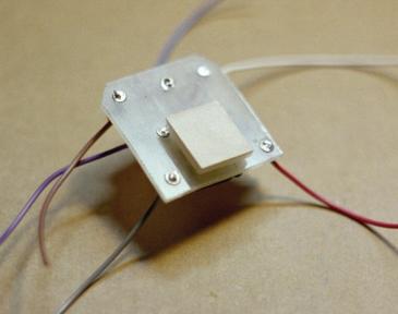
Flip your circuit board over and install the nylon standoff. Do not
remove the paper backing yet.
Step 8:
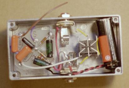
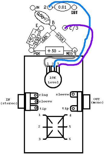
Trim the gray, blue, and purple wires so that they are long enough to connect with the solder llugs of the 10K pot.
Measure the wires with the circuit board upsidedown and with the edge of the circuit board with the bevelled corners
meeting the top edge of the enclosure. (see picture below) Strip 3mm of the ends of each wire. Solder the gray wire
coming off the "NEG" eyelet of the circuit board to LUG 1 of the 10K pot wire is will meet with the black battery wire.
Solder the blue wire coming off the "2" eyelet of the circuit board to to LUG 2 of the 10K pot. Solder the purple wire
coming off the "C/3" eyelet of the circuit board to LUG 3 of the 10K pot.
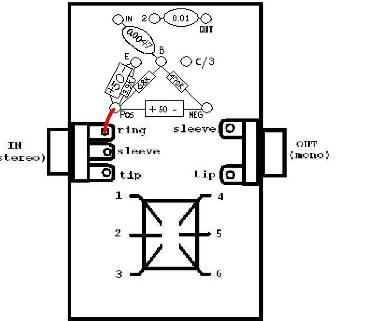
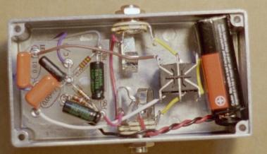
Step 9:
Remove the paper backing from the self-adhesive standoff. Flip the circuit board over and adhere the standoff to the
back of the 10K pot. Trim the red wire coming off the "POS" eyelet of the circuit board so that it is long enough to
connect to the RING of the IN JACK. Strip 3mm off of the end and solder the red wire to the ring of the in jack. Make
this wire as short as possible, but don't trim it so short that you are not able to strip the end of it. You pedal should
look like the picture below when you are finished with step 9.
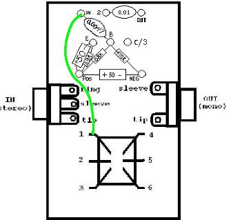
Step 10:
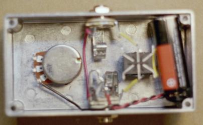
Trim the white wire coming off the "IN" eyelet of the circuit board so that it is long enough to connect to LUG 1 of the
footswitch. NOTE: The color green is used to represent the white wire in the diagram. Strip 3mm off the end of the
white wire and solder it to LUG 1 of the footswitch. Your pedal should look like the picture below when you are done
with step 10.
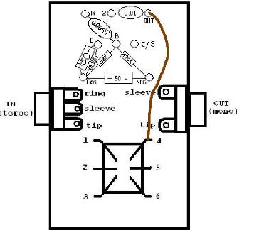
Step 11:
This is it...the last step! Trim the brown wire coming off the "OUT" eyelet of the circuit board so that it is long enough
to connect to LUG 4 of the footswitch. Strip 3mm off the end of the brown wire and solder it to lug 4 fo the footswitch.
Your pedal should look like the picture below when you are finished with step 11.
CONGRATULATIONS! you are finished building your pedal. You just need to do a few minor
things like put the lid and feet on. Check out the finishing touches section and then go play.