
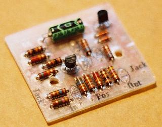
Step 1:
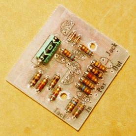
Add the diodes. Make sure that the black stripe is facing the
correct direction.


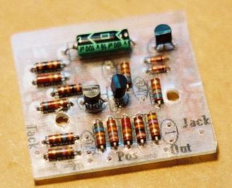
Step 4:
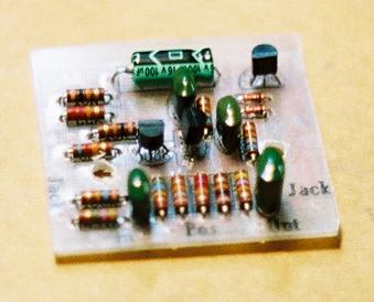
Add the two 2N5088 transistors. Insert them as pictured on your layout sticker.

Step 5:
Add the 2N3906 transistor. Insert it as pictured on your layout sticker.


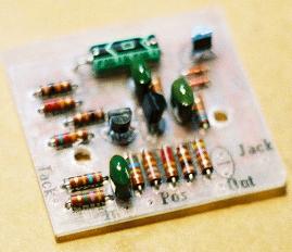
Step 7:
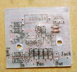
Add the 0.1uF capacitor. It will be labelled 104K. It does not matter what direction it goes in.