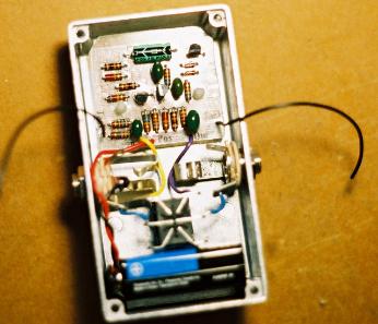

Step 5:
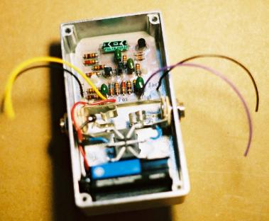
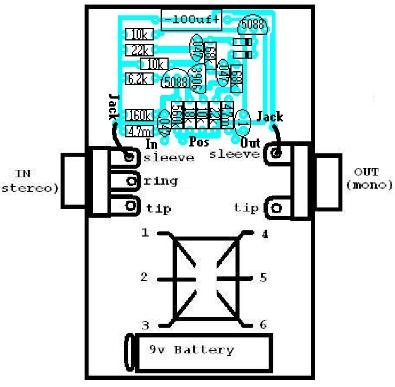
Insert the Circuit board into the enclose as pictured below, but do not remove the
paper backings yet.
Connect the battery snap to a 9v battery and install it in the place where it will goes.
Do this so you can better judge how long to make the battery wires before you trim
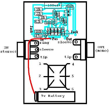
them. Measure the black battery wire so that it is long enough to reach the "Ring" of
the IN jack but leave enough slack so that it will be easy to change the battery. Strip
3mm off the end of the black battery wire and solder it to the Ring of the IN jack.
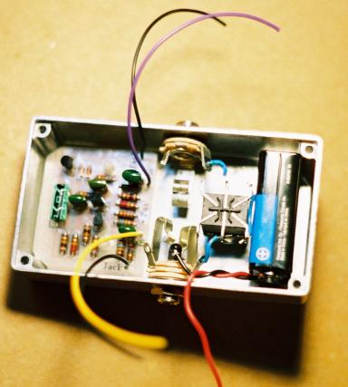
Step 6:
Measure and trim the red battery wire so that it is the proper lenght to reach the hole in the circuit board labelled
POS. Strip 3mm off the end of the red wire. Remove the circuit board from the enclosure and solder the red wire
to the hole labelled POS. Now remove the paper backings from the nylon standoffs and install the circuit board to
the enclosure.
Step 7:
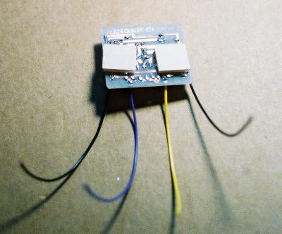
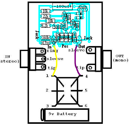
Measure and trim the yellow wire that is soldered to the "In" hole on the circuit board so that it is the proper length to
reach LUG1 of the footswitch. Strip 3mm off the end and solder it to LUG1. Do the same for the purple wire that is
soldered to the "Out" hole on the circuit board so that it is the proper length to reach LUG 4 of the footswitch. Strip
3mm off the end of the purple wire and solder it to LUG 4
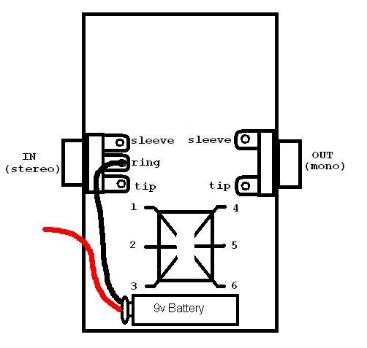
Step 8:
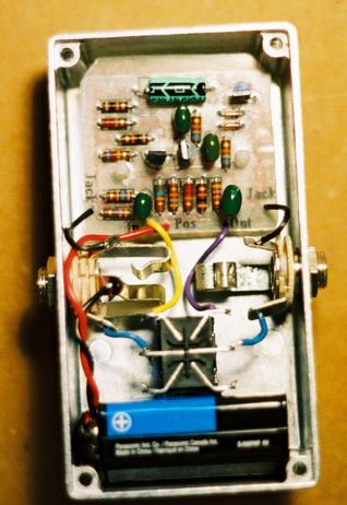
Measure and trim each of the black wires that are soldered to the "Jack" holes on the circuit board so that
each is long enough to reach the "Sleeves" of the jacks that they are closest to. So the black wire on the
right would go to the sleeve of the OUT jack and the black wire on the left would go to the sleeve of the IN
jack. Strip 3mm of the end of each black wire and solder them to their respective sleeves.
Your basically done now. Just go back to the instruction index
and click on "Finishing Touches and Trouble shooting".