
Step 8:
Add the 10k trim pot. This will adjust the bias of the JFET.
Step 10:
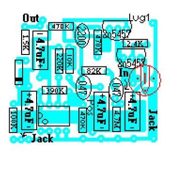
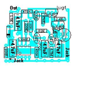
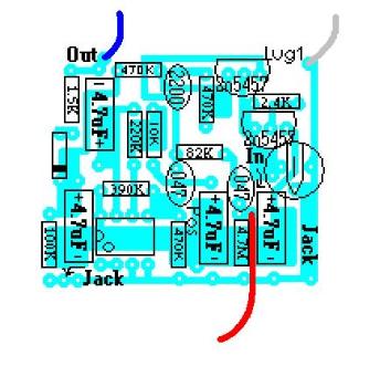
Strip 3mm off the ends of the blue, gray, and white wires. Add them to the circuit board. The blue wire goes to the
hole labelled "out". The Gray wire goes to the hole labelled "lug 1". And the white wire goes to the hole labelled
"IN". Note: the white wire is depiceted as red in the diagram below so that it is easier to see.
Step 11:
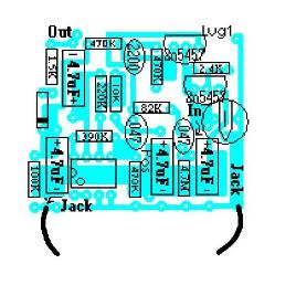
Cut the black wire in half and strip 3mm off the end of each half. Solder one black wire to each of the holes labelled
"Jack".
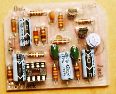
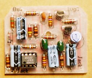
You are finished with the "populating the circuit board" portion of the directions.
Now continue with the "wiring" section.