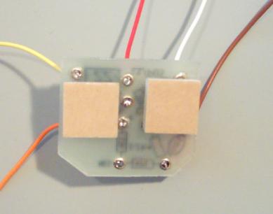
Step 1:
Insert the Standoffs into the underside of the Circuit board, but
DO NOT peel off the self-adheasive backings yet.
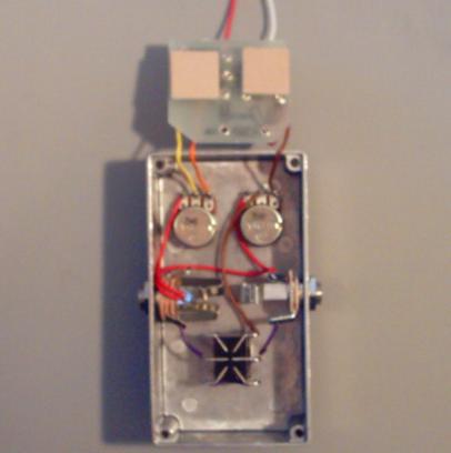
Step 2:
With the circuit board UPSIDE DOWN, measure and trim the
YELLOW, ORANGE, and BROWN wires so that they are about
2 inches long.  Strip 3mm off the ends of each wire.  Then
solder the
BROWN wire to LUG 3 of the 500K pot.  Solder the
ORANGE wire to LUG 3 of the 1K pot.  Solder the YELLOW
wire to LUG 2 of the 1K pot.  Your pedal should look like the
picture below when you are finished with step 2.
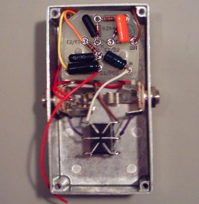
Step 3:
Remove the backings off the self-adhesive standoffs.  Flip the circuit board right side up and secure the stand offs to
the back of the 2 potentiometers.  Bend the yellow, orange and brown wires so that they fit into the corner spaces of
the enclosure.

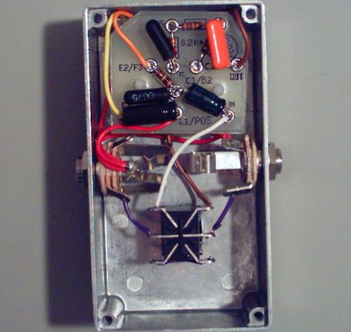
You are now finished with the "adding the circuit board" section of building your pedal.  
Click here to continue on to the "battery" section.

Adding the Circuit Board

Step 4:
Measure and trim the WHITE wire from the "IN" eyelet of the circuit board so that it is the proper length to connect to
LUG 1 of the footswitch.  Strip 3mm off the end of the WHITE wire and solder it to LUG 1 of the footswitch.  Your
pedal should look like the picture below when you are finished with step 5.

Step 5:
Measure and trim the RED wire from the E1/POS eyelet of the circuit board so that it is the proper length to connect to
the
SLEEVE of the IN jack.  Strip 3mm off the end of the RED wire and solder it to the SLEEVE of the IN jack.  Just
like the last time you added a wire to an existing joint, heat the joint till the existing solder melts.  Then insert the
stripped wire into the solder lug of the SLEEVE of the IN jack.  When all the wires are in place, add a touch of new
solder to make sure the joint is a good weld.  Your pedal should look like the picture below when you are done with
step 5.