

Step 4:
Insert the 100K resistor (brown/black/yellow) and the 2.2uF
capacitor into their proper positions. The 2.2uf cap is polarized
so it must be facing the correct way. There are "+" symbols on
the capcitor that tell which end is positive and which end is
negative. The negative end should meet with the Base of
Transistor 1 and the 100K resistor.

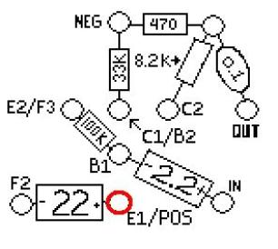
Solder only where the 3 components meet. The red circle
shows the eyelet where to solder.
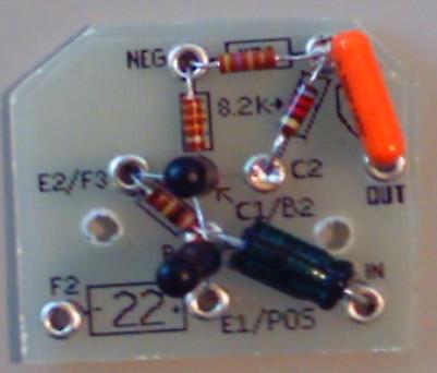
This is what your circuit board should look like after step 4.
Step 5:
Insert the 22uF capacitor into its proper position. Like the 2.2uF
cap, the 22uF cap is also polarized. You must make sure that it
is facing the right direction. The positive end should meet with
the Emitter of Transistor 1 (E1). Now all of the components are
in place. You will now begin to add the hook-up wire to the
circuit board. Take a 3" strand of the red wire and strip 3mm off
one end. Insert the stripped end of the red wire into the eyelet
where the positive end of the 22uF capacitor and E1 meet. This
red wire will supply the positive current for the circuit (POS).
The red circle shows the eyelet where the 2 components and the
red wire meet. This is where you should solder.
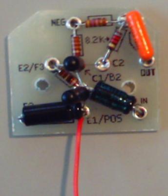
This is what your circuit board should look like after step 5.
Step 6:
Take the 3" strand of brown wire and strip 3mm off one end.
Insert the stripped end into the unsoldered eyelet of the
0.1uF capacitor marked OUT. The brown wire will be the
"signal out".

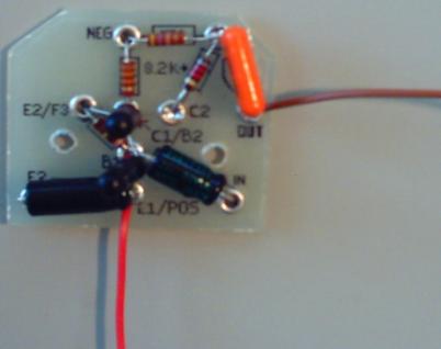
This is what your circuit board should look like after step 6.
