

Step 7:
Strip 3 milimeters of one end of the 3 inch strand of white
wire. Insert the stripped end into the eyelet marked IN that
meets the positive end of the 2.2 uF capacitor. This will be
the "signal in".

The red circle shows the eyelet where you should solder the
white wire to the positive end of the 2.2 uF cap.
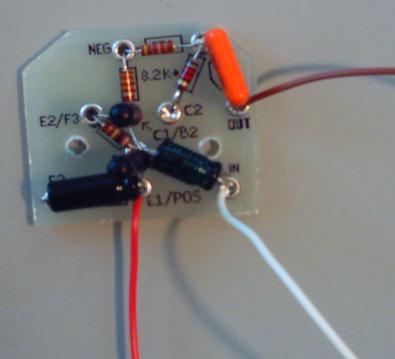
This is what your curcuit board should look like after step 7.
Step 8:
Strip 2 millimeters off of one end of the 3 inch strand of
yellow wire. Insert the stripped end in the eyelet that is
marked F2 where it meets the negative end of the 22 uF
capacitor. This wire will go to the center log of the fuzz
potentiometer.
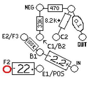
The red circle shows "F2". This is the eyelet where you
should solder the yellow wire to the negative end of the 22uF
capacitor.
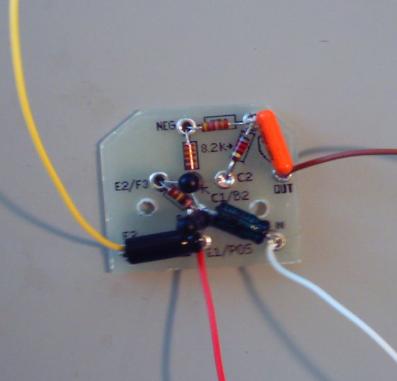
This is what your curcuit board should look like after step 8.
Step 9:
Strip 3 millimeters off one end of the 3 inch strand of orange
wire. Insert the stripped end into the eyelet labeled "E2/F3"
where it meets the unsoldered end of the 100K resistor. This
wire will go to lug three of the fuzz potentiometer.

The red circle shows the eyelet marked E2/F3. This is where
you should solder the orange wire to the 100K resistor.
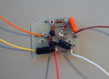
This is what your curcuit board should look like after step 9.
This completes the circuit board populating
process. Click here to continue on to the
assembly.
