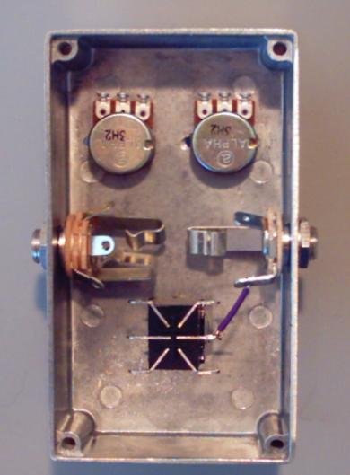
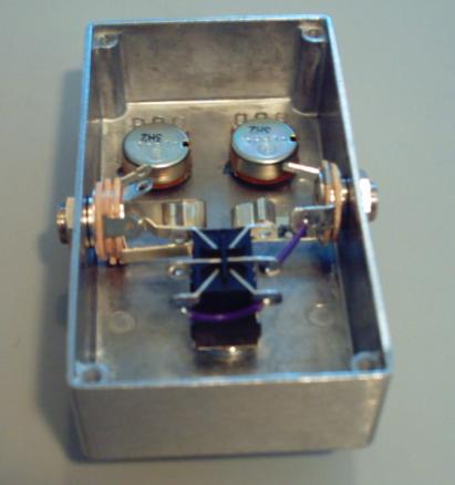
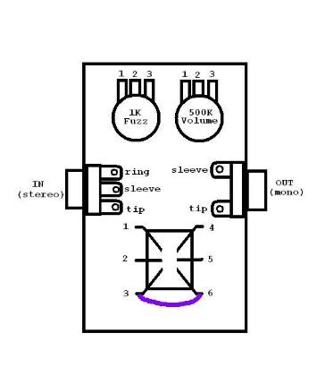
Step 2:
Measure out enough purple wire to connect LUG 6 of the footswitch to LUG 3 of the footswitch.  This should also
be less then 1" of wire, but once again, use as little as you are comfortable with.  Strip 3mm off each end of the strand
of purple wire and solder.  Your pedal should look like the picture below after step 2.
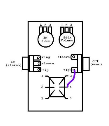
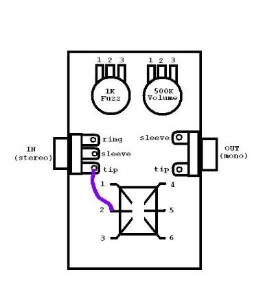
Step 3:
Measure out enough purple wire to connect LUG 2 of the footswitch to the TIP of the IN jack.  This should only
require about 1" of purple wire.  Strip 3mm off each end of the wire and then solder.  Your pedal should look like the
picture below when you are done with step 3.

Click here to continue on to the "Jacks and Ground" section of the
Wiring Process.

Switch & Jacks

We are now ready to begin the wiring process of building your
pedal.  This is where most mistakes are made, so just take
your time, follow the instructions, and think about what it is you
are doing before you do it.  You should also take the time to
compare this diagram to your pedal that already has the
switch, jacks, and pots assembled and become familiar with
where all the soldering lugs are.   Particularly the jacks.  You
can learn a lot about the jacks by actually inserting a 1/4"
cable plug into them and seeing where and how contacts are
made.

Step 1:  
Measure out enough purple wire to connect LUG 5 of the footswitch to the TIP of the OUT jack.  You want to
keep your wires as short as possible.  Shorter wires mean less hum.  It should take less than 1" of purple wire to
connect LUG 5 with the TIP of the OUT jack.  But if you have trouble working with such short wire, then use as little
as you can and still be able to work comfortably.  Strip 3mm from each end of the measured strand of purple wire
and solder.  Your pedal should look like the picture below after step 1.