
Before you begin solder, keep in mind that when you are done,
you will need to bend some of the components down so that the
lid will fit. So when you are positioning your components,
particularly the transistors and the orange capacitors, make sure
that they will have enough lead sticking up out of the eyelets so
thay you can bend them without braking them. You don't need
much...in fact, you'll probably get the perfect length if you just
avoid trying to cram the components into the eyelets are far as
they'll go.
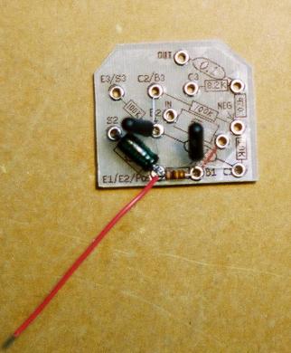
Step 1:
This is a tricky one. You've got 5 different components being
soldered to the same eyelet in this step so take your time and
study the diagrams before you clip, bend, or solder anything.
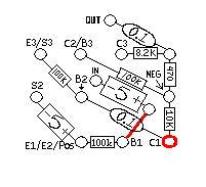
Solder E1, E2, 100k (brown/black/yellow), 5uF, and 4 inches of
red wire to the eyelet that is highlighted in red in the diagram
below. Make sure that both of the emitters of transistor 1 and
transistor 2 meet at this solder joint. Also make sure that the
positive end of the 5uf cap is soldered at this eyelet as well.
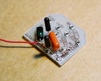
Your circuit board should look like the photo below when you
are done with step 1. (Note: Save the excess lead wire that you
clip off of the 5uF cap. You will need it for the next step.

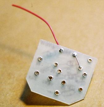
Step 2:
Using the excess lead wire that you clipped off the 5uF cap from the last step, make a "bare bus wire" to run on the
underside of the circuit board. The red line on your circuit board layout sticker represents this. Solder only the
eyelet that is highlighted in red. Your circuit board should look like the pic below when you are done with step 2.

Step 3:
Solder one of the 0.1uF Orange Drop capacitors and the 10K (brown/black/orange) resistor to the eyelet
highlighted in red in the diagram below. Your circuit board should look like the picture below when you are
done with step 3.
Step 4:
Solder the Base of transistor 2 (B2) and one of the 100K (brown/black/yellow) resistors to the eyelet
highlighted in red in the diagram below. Your circuit board should look like the pic below when you are
finished with step 4.

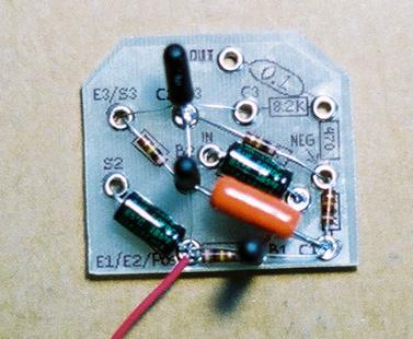
Step 5:
Solder the other 5uF capacitor to the eyelet highlighted in red where it meets with the other end of the bus
wire. Make sure that the positive end of the capacitor goes to this eyelet. Your circuit board should look
like the pic below when you are done with step 5.


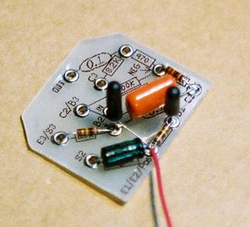
Step 6:
Solder the Collector of Transistor 2 (C2), the Base of Transistor 3 (C3), and the last 100K (brown/black/yellow)
resistor to the eyelet highlighted in red in the diagram below. Your circuit board should look like the picture
below when you are finished with step 6.