Step2:
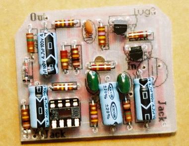
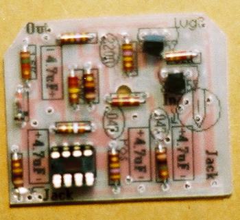
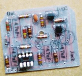
Add the germanium diode.  Make sure that the
black line is facing the correct direction.

Step 3:
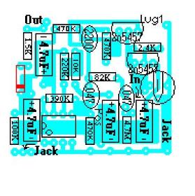
Add the 8 pin socket.  For your own reference, orientate the socket so that the side with "U" shaped cut out matches
the image on the circuitboard layout sticker.
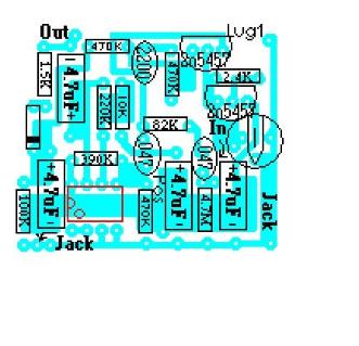
Step 4:
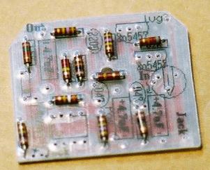
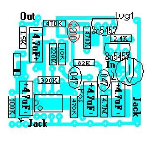
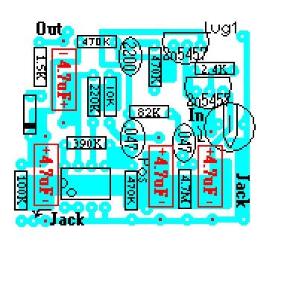
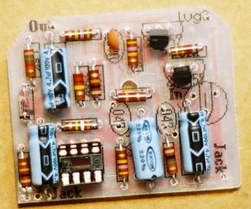
Add the two 2N5457 JFETs.  Make sure that the flat side of the JFETs match with the image on the layout sticker.

Step 7:
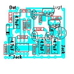
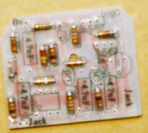
Add the .047uF metal film caps.  They will be marked 473K.  These are not polarized so it does not matter how they are
orientated.

Populating the circuit board Steps 1 - 7

Step 1:
Add all resistors.  Resistors are not polarized so
it does not matter which direction you orientate
them

1.5k - brown/green/red/gold
2.4k - red/yellow/red/gold
10k - Brown/black/orange/gold
82k - gray/red/orange/gold
100k - brown/black/yellow/gold
220k - red/red/yellow/gold
390k - orange/white/yellow/gold
470k - yellow/purple/yellow/gold
4.7m - yellow/purple/green/gold

Step 5:
Add the 2200pF (pico farads) ceramic disc capacitor.  This cap is not polarized, so it makes no difference which way
it's orientated.

Step 6:
Add the four 4.7uF(micro farads) aluminum electrolytic capacitors.  These are polarized so make sure that the positive
and negative ends are orientated correctly.  The stripe of black arrows point to the negative end.  Or you can also
identify the positive end as the end with the rubber seal.

Click here to continue to step 8