
Step 4:
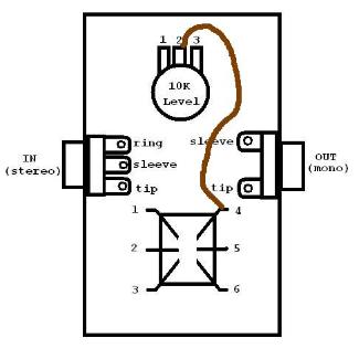
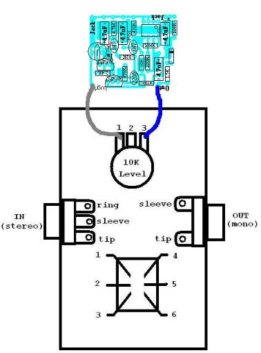
Measure and trim the brown wire so that it is the proper lenght
to connect LUG2(center lug) of the 10K pot to lug 4 of the
footswitch. Strip 3mm off each and and solder. Note: The 10K
pot will have an adheasive backing. DO NOT remove the
backing yet.
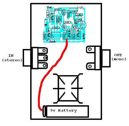
Step 7:
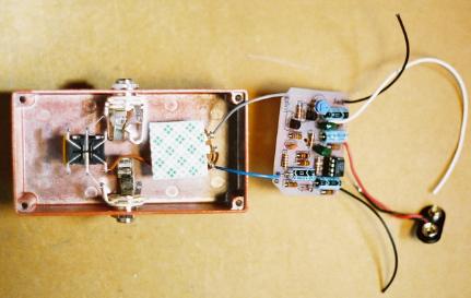
Twist the circuit board and then flip it over and put it back in the enclosure, but still do not attatch it to the
adheasive backing. Measure and trim the black battery wire so that it is the proper lenght to reach the ring of the
IN jack. Make sure it has enough slack so that it will be easy to change the battery. Strip 3mm off the end of the
black wire and solder it to the ring of the IN jack.
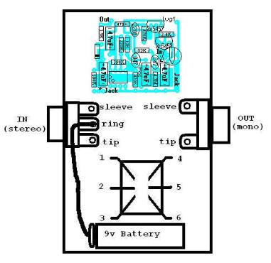
Step 8:
Measure and trim the white wire connected to the hole in the circuit board labelled "in" so that it is the proper length to
connect to LUG 1 of the footswitch. Strip 3mm off the end of the white wire and solder it to LUG1 of the footswitch.